
The Concrete Design add-on provides you with the option to perform the simplified fire resistance design according to EN 1992‑1‑2 for columns (Section 5.3.2) and beams (Section 5.6).
The following design checks are available for the simplified fire resistance design:
- Columns: Minimum cross-sectional dimensions for rectangular and circular sections according to Table 5.2a as well as Equation 5.7 for calculating time of fire exposure
- Beams: Minimum dimensions and center distances according to Table 5.5 and Table 5.6
You can determine the internal forces for the fire resistance design according to two methods.
- 1 Here, the internal forces of the accidental design situation are included directly into the design.
- 2 The internal forces of the design at normal temperature are reduced by the factor Eta,fi (ηfi), then used in the fire resistance design.
Furthermore, it is possible to modify the axis distance according to Eq. 5.5.

With the Concrete Design add-on, you can perform the fatigue design of members and surfaces according to EN 1992‑1‑1, Chapter 6.8.
For the fatigue design, you can optionally select two methods or design levels in the design configurations:
- Design Level 1: Simplified design according to 6.8.6 and 6.8.7(2): The simplified design is performed for frequent action combinations according to EN 1992‑1‑1, Chapter 6.8.6 (2), and EN 1990, Eq. (6.15b) with the traffic loads relevant in the serviceability state. A maximum stress range according to 6.8.6 is designed for the reinforcing steel. The concrete compressive stress is determined by means of the upper and lower allowable stress according to 6.8.7(2).
- Design Level 2: Design of damage equivalent stress acc. to 6.8.5 and 6.8.7(1) (simplified fatigue design): The design using damage equivalent stress ranges is performed for the fatigue combination according to EN 1992‑1‑1, Chapter 6.8.3, Eq. (6.69) with the specifically defined cyclic action Qfat.

Use RWIND 2 Pro to easily apply a permeability to a surface. All you need is the definition of
- the Darcy coefficient D,
- the inertial coefficient I, and
- the length of the porous medium in the direction of flow L,
to define a pressure boundary condition between the front and back of a porous zone. Due to this setting, you obtain the flow through this zone with a two-part result display on both sides of the zone area.
But that's not all. Furthermore, the generation of a simplified model recognizes permeable zones and takes into account the corresponding openings in the model coating. Can you waive an elaborate geometric modeling of the porous element? Understandable – we have good news for you then! With a pure definition of the permeability parameters, you can avoid complex geometric modeling of the porous element. Use this feature to simulate permeable scaffolding, dust curtains, mesh structures, and so on.
More Information
- Calculation of deflections and comparison with the normative or manually adjusted limit values
- Consideration of a precamber for the deflection analysis
- Different limit values are possible, depending on the design situation type
- Manual adjustment of reference lengths and segmentation by direction
- Calculation of deflections related to the initial structure or to the deformed structure
- Automatic consideration of time-dependent deformations by increasing the load with the creep factor (can also be user-defined on the stiffness side)
- Simplified vibration design
- Graphical result display integrated in RFEM/RSTAB; for example, the design ratio of a limit value, the deformation, or the sag
- Complete integration of the results into the RFEM/RSTAB printout report

- Calculation of stationary incompressible turbulent wind flow using the SimpleFOAM solver from the OpenFOAM® software package
- Numerical scheme according to the first and second order
- Turbulence models RAS k-ω and RAS k-ε
- Consideration of surface roughness depending on model zones
- Model design via VTP, STL, OBJ, and IFC files
- Operation via bidirectional interface of RFEM or RSTAB for importing model geometries with standard-based wind loads and exporting wind load cases with probe-based printout report tables
- Intuitive model changes via drag & drop and graphical adjustment assistance
- Generation of a shrink-wrap mesh envelope around the model geometry
- Consideration of environmental objects (buildings, terrain, and so on)
- Height-dependent description of the wind load (wind speed and turbulence intensity)
- Automatic meshing depending on a selected depth of detail
- Consideration of layer meshes near the model surfaces
- Parallelized calculation with optimal utilization of all processor cores of a computer
- Graphical output of the surface results on the model surfaces (surface pressure, Cp coefficients)
- Graphical output of the flow field and vector results (pressure field, velocity field, turbulence – k-ω field, and turbulence – k-ε field, velocity vectors) on Clipper/Slicer planes
- Display of 3D wind flow via animated streamline graphics
- Definition of point and line probes
- Multilingual user interface (German, English, Czech, Spanish, French, Italian, Polish, Portuguese, Russian, and Chinese)
- Calculations of several models in one batch process
- Generator for creating rotated models to simulate different wind directions
- Optional interruption and continuation of the calculation
- Individual color panel per result graphic
- Display of diagrams with separate output of results on both sides of a surface
- Output of the dimensionless wall distance y+ in the mesh inspector details for the simplified model mesh
- Determination of the shear stress on the model surface from the flow around the model
- Calculation with an alternative convergence criterion (you can select between the residual types pressure or flow resistance in the simulation parameters)

Compared to the RF-/STEEL Warping Torsion add-on module (RFEM 5 / RSTAB 8), the following new features have been added to the Torsional Warping (7 DOF) add-on for RFEM 6 / RSTAB 9:
- Complete integration into the environment of RFEM 6 and RSTAB 9
- 7th degree of freedom is directly taken into account in the calculation of members in RFEM/RSTAB on the entire system
- No more need to define support conditions or spring stiffnesses for calculation on the simplified equivalent system
- Combination with other add-ons is possible, for example for the calculation of critical loads for torsional buckling and lateral-torsional buckling with stability analysis
- No restriction to thin-walled steel sections (it is also possible to calculate ideal overturning moments for beams with massive timber sections, for example)

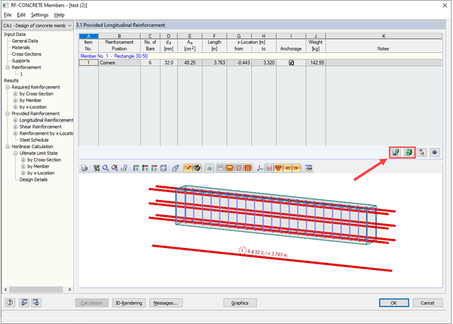
- Determination of longitudinal, shear, and torsional reinforcement
- Representation of minimum and compression reinforcement
- Determination of neutral axis depth, concrete and steel strains
- Design of member sections affected by bending about two axes
- Design of tapered members
- Design of RSECTION cross-sections (see this Product Feature)
- Determination of deformation in state II; for example, according to EN 1992‑1‑1, 7.4.3, and ACI 318‑19 24.2.3, Table 24.2.3.5
- Considering tension stiffening
- Considering creep and shrinkage
- Fatigue design according to EN 1992‑1‑1, Section 6.8 (see this Product Feature)
- Simplified fire resistance design according to EN 1992‑1‑2 for Columns (Section 5.3.2) and Beams (Section 5.6) (see this Product Feature)
- Seismic design according to EC 8 (see this Product Feature)
- Precise breakdown of reasons for failed design
- Design details of all design locations for better traceability of reinforcement determination
- Optional cross-section optimization
- Visualization of concrete section with reinforcement in 3D rendering
- Creation of 2D interaction diagrams; for example, M-N diagram
- Visualization of section resistance in 3D interaction diagram
- Output of moment-curvature diagram
- Full integration in RFEM/RSTAB with import of geometry and load case data
- Automatic selection of members for design according to specified criteria (e.g. only vertical members)
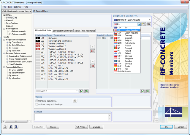
- In connection with the extension EC2 for RFEM/RSTAB, you can perform the design of reinforced concrete compression elements according to the method based on nominal curvature in compliance with EN 1992 -1‑1:2004 (Eurocode 2) and the following National Annexes:
-
 DIN EN 1992-1-1/NA/A1:2015-12 (Germany)
 -
 ÖNORM B 1992-1-1:2018-01 (Austria)
 -
 Belgium NBN EN 1992-1-1 ANB:2010 for design at normal temperature, and NBN EN 1992-1-2 ANB:2010 for fire resistance design (Belgium)
 -
 BDS EN 1992-1-1:2005/NA:2011 (Bulgaria)
 -
 EN 1992-1-1 DK NA:2013 (Denmark)
 -
 NF EN 1992-1-1/NA:2016-03 (France)
 -
 SFS EN 1992-1-1/NA:2007-10 (Finland)
 -
 UNI EN 1992-1-1/NA:2007-07 (Italy)
 -
 LVS EN 1992-1-1:2005/NA:2014 (Latvia)
 -
 LST EN 1992-1-1:2005/NA:2011 (Lithuania)
 -
 MS EN 1992-1-1:2010 (Malaysia)
 -
 NEN-EN 1992-1-1+C2:2011/NB:2016 (Netherlands)
 -
 NS EN 1992-1 -1:2004-NA:2008 (Norway)
 -
 PN EN 1992-1-1/NA:2010 (Poland)
 -
 NP EN 1992-1-1/NA:2010-02 (Portugal)
 -
 SR EN 1992-1-1:2004/NA:2008 (Romania)
 -
 SS EN 1992-1-1/NA:2008 (Sweden)
 -
 SS EN 1992-1-1/NA:2008-06 (Singapore)
 -
 STN EN 1992-1-1/NA:2008-06 (Slovakia)
 -
 SIST EN 1992-1-1:2005/A101:2006 (Slovenia)
 -
 UNE EN 1992-1-1/NA:2013 (Spain)
 -
 CSN EN 1992-1-1/NA:2016-05 (Czech Republic)
 -
 BS EN 1992-1-1:2004/NA:2005 (United Kingdom)
 -
 TKP EN 1992-1-1:2009 (Belarus)
 -
 CYS EN 1992-1-1:2004/NA:2009 (Cyprus)
-
- In addition to the National Annexes (NA) listed above, you can define a specific NA, applying user-defined limit values and parameters.
- Optional consideration of creep
- Diagram-based determination of buckling lengths and slenderness from the restraint ratios of columns
- Automatic determination of ordinary and unintentional eccentricity from additionally available eccentricity according to the second-order analysis
- Design of monolithic structures and precast elements
- Analysis with regard to the standard reinforced concrete design
- Determination of internal forces according to the linear static analysis and the second-order analysis
- Analysis of governing design locations along the column due to existing loading
- Output of required longitudinal and stirrup reinforcement
- Fire resistance design according to the simplified method (zone method) according to EN 1992-1-2 allowing the fire resistance design of brackets.
- Fire resistance design with optional longitudinal reinforcement design according to DIN 4102-22:2004 or DIN 4102-4:2004, Table 31
- Longitudinal and link reinforcement proposal with graphic display in 3D rendering
- Summary of design ratios, including all design details
- Graphical representation of relevant design details in RFEM/RSTAB work window
The nonlinear calculation adopts the real mesh geometry of planar, buckled, simple curved, or double curved surface components from the selected cutting pattern and flattens this surface component in compliance with the minimization of distortion energy, assuming defined material behavior.
In simplified terms, this method attempts to compress the mesh geometry in a press, assuming frictionless contact, and to find the state in which the stresses from flattening in the component are in equilibrium in the plane. This way, minimum energy and optimum accuracy of the cutting pattern are achieved. Compensation for warp and weft as well as compensation for boundary lines are considered. Then, the defined allowances on boundary lines are applied to the resulting planar surface geometry.
Features:
- Minimization of distortion energy in the flattening process for very accurate cutting patterns
- Application for almost all mesh arrangements
- Recognition of adjacent cutting pattern definitions to keep the same length
- Mesh application for main calculation
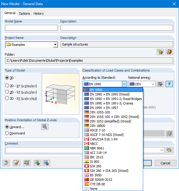
The Base Data dialog box includes a wide range of standards and the option to create combinations automatically. The following standards are available:
-
 EN 1990:2002
 -
EN 1990 + EN 1995:2004 (Timber)
-
EN 1990 + EN 1991-2; Road bridges
-
EN 1990 + EN 1991-3; Cranes
-
EN 1990 + EN 1997
-
to DIN 1055-100:2001-03
-
DIN 1055-100 + DIN 1052:2004-08 (timber)
-
DIN 1055-100 + DIN 18008 (Glass)
-
DIN 1052 (simplified) (timber)
-
DIN 18800:1990
-
 ASCE 7‑10
 -
ASCE 7-10 NDS (Wood)
-
ACI 318-14
-
IBC 2015
-
 CAN/CSA S 16.1-94:1994
 -
NBCC: 2005
-
 NBR 8681
 -
 IS 800:2007
 -
 SIA 260:2003
 -
SIA 260 + SIA 265:2003 (timber)
-
BS 5950-1:2000
-
 GB 50009-2012
 -
CTE DB-SE
For the European standards (EC), the following National Annexes are available:
-
DIN EN 1990/NA:2009-05 (Germany)
-
NBN EN 1990 - ANB: 2005 (Belgium)
-
BDS EN 1990:2003/NA:2008 (Bulgaria)
-
DK EN 1990/NA:2007-07 (Denmark)
-
SFS EN 1990/NA:2005 (Finland)
-
NF EN 1990/NA:2005/12 (France)
-
 ELOT EN 1990:2009 (Greece)
 -
UNI EN 1990/NA:2007-07 (Italy)
-
 IS EN 1990:2002 + NA:2010 (Ireland)
 -
LVS EN 1990:2003/NA:2010 (Latvia)
-
LST EN 1990/NA:2010-11 (Lithuania)
-
 LU EN 1990/NA:2011-09 (Luxembourg)
 -
MS EN 1990:2010 (Malaysia)
-
NEN EN 1990/NA:2006 (Netherlands)
- NS EN 1990/NA:2008 (Norway)
-
ÖNORM EN 1990:2007-02 (Austria)
-
NP EN 1990:2009 (Portugal)
-
PN EN 1990/NA:2004 (Poland)
-
SR EN 1990/NA:2006-10 (Romania)
-
SIST EN 1990: 2004/A1:2005 (Slovenia)
-
SS EN 1990:2008 (Singapore)
-
SS EN 1990/BFS 2010:28 (Sweden)
-
STN EN 1990/NA:2009-08 (Slovakia)
-
UNE EN 1990 2003 (Spain)
-
CSN EN 1990/NA:2004-03 (Czech Republic)
-
BS EN 1990/NA:2004-12 (the United Kingdom)
-
TKP EN 1990/NA:2011 (Belarus)
-
CYS EN 1990:2002 (Cyprus)
Before the calculation starts, you should check the input data using the program function. Then, the CONCRETE add‑on module searches the results of relevant load cases, load as well as result combinations. If these cannot be found, RSTAB starts the calculation to determine the required internal forces.
Considering the selected design standard, the required reinforcement areas of the longitudinal and the shear reinforcement as well as the corresponding intermediate results are calculated. If the longitudinal reinforcement determined by the ultimate limit state design is not sufficient for the design of the maximum crack width, it is possible to increase the reinforcement automatically until the defined limit value is reached.
The design of potentially unstable structural components is possible using a nonlinear calculation. According to a respective standard, different approaches are available.
The fire resistance design is performed according to a simplified calculation method in compliance with EN 1992‑1‑2, 4.2. The module uses the zone method mentioned in Annex B2. Furthermore, you can consider the thermal strains in the longitudinal direction and the thermal precamber additionally arising from asymmetrical effects of fire.
- Import of results from RSTAB
- Integrated material and cross-section library
- The module extension EC2 for RSTAB enables design of reinforced concrete according to EN 1992-1-1 (Eurocode 2) and the following National Annexes:
-
DIN EN 1992-1-1/NA/A1:2015-12 (Germany)
-
ÖNORM B 1992-1-1:2018-01 (Austria)
-
Belgium NBN EN 1992-1-1 ANB:2010 for design at normal temperature, and NBN EN 1992-1-2 ANB:2010 for fire resistance design (Belgium)
-
BDS EN 1992-1-1:2005/NA:2011 (Bulgaria)
-
EN 1992-1-1 DK NA:2013 (Denmark)
-
NF EN 1992-1-1/NA:2016-03 (France)
-
SFS EN 1992-1-1/NA:2007-10 (Finland)
-
UNI EN 1992-1-1/NA:2007-07 (Italy)
-
LVS EN 1992-1-1:2005/NA:2014 (Latvia)
-
LST EN 1992-1-1:2005/NA:2011 (Lithuania)
-
MS EN 1992-1-1:2010 (Malaysia)
-
NEN-EN 1992-1-1+C2:2011/NB:2016 (Netherlands)
- NS EN 1992-1 -1:2004-NA:2008 (Norway)
-
PN EN 1992-1-1/NA:2010 (Poland)
-
NP EN 1992-1-1/NA:2010-02 (Portugal)
-
SR EN 1992-1-1:2004/NA:2008 (Romania)
-
SS EN 1992-1-1/NA:2008 (Sweden)
-
SS EN 1992-1-1/NA:2008-06 (Singapore)
-
STN EN 1992-1-1/NA:2008-06 (Slovakia)
-
SIST EN 1992-1-1:2005/A101:2006 (Slovenia)
-
UNE EN 1992-1-1/NA:2013 (Spain)
-
CSN EN 1992-1-1/NA:2016-05 (Czech Republic)
-
BS EN 1992-1-1:2004/NA:2005 (United Kingdom)
-
CPM 1992-1-1:2009 (Belarus)
-
CYS EN 1992-1-1:2004/NA:2009 (Cyprus)
-
- In addition to the National Annexes (NA) listed above, you can also define a specific NA, applying user‑defined limit values and parameters.
- Optional presetting of partial safety factors, reduction factors, neutral axis depth limitation, material properties, and concrete cover
- Determination of longitudinal, shear, and torsional reinforcement
- Design of tapered members
- Cross‑section optimization
- Representation of minimum and compression reinforcement
- Determination of editable reinforcement proposal
- Crack width analysis with optional increase of the required reinforcement in order to keep the defined limit values of the crack width analysis
- Nonlinear calculation with consideration of cracked cross‑sections (for EN 1992‑1‑1:2004 and DIN 1045‑1:2008)
- Considering tension stiffening
- Considering creep and shrinkage
- Deformations in cracked sections (state II)
- Graphical representation of all result diagrams
- Fire resistance design according to the simplified method (zone method) according to EN 1992‑1‑2 for rectangular and circular cross‑sections. Thus, fire resistance design of brackets is possible as well.
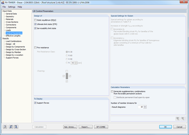
In RX-TIMBER Brace, the following settings for the calculation can be made:*Selection of the designs to be performed
- Determination of displaying support forces and deformations
- Adjustment of recommended limit values for deformation analyses in the ultimate and the serviceability limit state design
- Free definition of parameters for the fire resistance design performed according to the simplified method
- Consideration of material nonlinearities (failing members)
You can define the design type to be performed in the Control Parameters window.
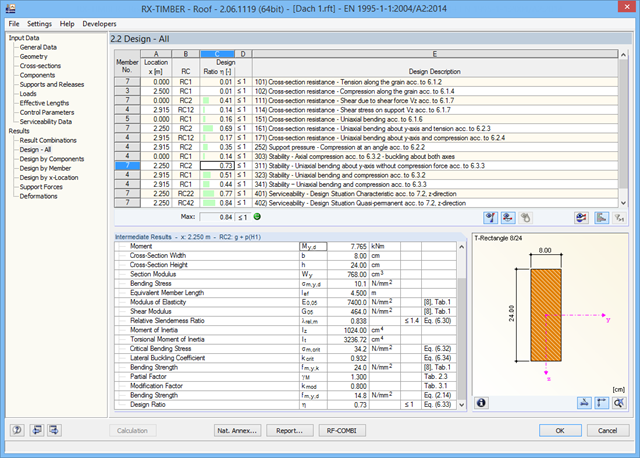
In RX-TIMBER Roof, you can set the following calculation specifications: *Selection of the designs to be performed (ULS, SLS, fire resistance)
- Determination of displaying support forces and deformations
- Adjusting the recommended limit values for the serviceability limit state
- Definition of parameters for fire resistance design according to the simplified method
- Increasing strengths according to EN 1995‑1‑1, Clause 3.2
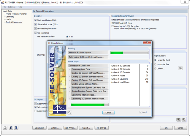
In RX-TIMBER Frame, the following calculation settings are available:
- Design of ULS, SLS, and/or fire resistance Selection of designs to be performed
- Determination of displaying support forces and deformations
- Adjusting the recommended limit values for the deformation analyses
- Free definition of parameters for the fire resistance design performed according to the simplified method
- Increasing bending stiffnesses for flat‑ended bending strains
Separate design cases allow for a flexible analysis of specific actions as well as for individual stability analyses. You can define the design type to be performed in the Control Parameters window.
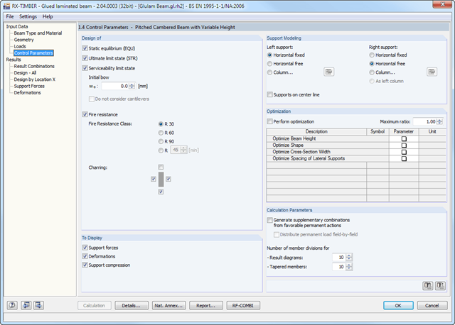
In RX-TIMBER Glued-Laminated Beam, the following calculation settings are available:
- Design of ULS, SLS, and/or fire resistance
- Selection of designs to be performed
- Determination of displaying support forces and deformations
- Adjusting the recommended limit values for the deformation analyses
- Definition of parameters for the fire resistance design performed according to the simplified method (optionally for F 30‑B, F 60‑B, F 90‑B, and user‑defined)
- Determination of tilting moment for pinned support
- Definition of support conditions for a beam
- Beam optimization by means of:
- Beam depth modification
- Modification of beam scene
- cross-section width
- Spacing of lateral supports
- Determination of longitudinal, shear, and torsional reinforcement
- Representation of minimum and compression reinforcement
- Determination of neutral axis depth, concrete and steel strains
- Design of member sections affected by bending about two axes
- Design of tapered members
- Determination of deformation in state II, for example according to EN 1992-1-1, 7.4.3
- Considering tension stiffening
- Considering creep and shrinkage
- Precise breakdown of reasons for failed design
- Design details of all design locations for better traceability of reinforcement determination
- Options to optimize cross‑sections
- Visualization of concrete section with reinforcement in 3D rendering
- Output of complete steel schedule
- Fire resistance design according to the simplified method (zone method) according to EN 1992‑1‑2 for rectangular and circular cross‑sections
- Optional extension of the RF‑CONCRETE Members add‑on module with a nonlinear calculation of frameworks for the ultimate and serviceability limit states. The extension enables the design of potentially unstable structural components by means of a nonlinear calculation, or a nonlinear deformation analysis of 3D frameworks. Find more information under the product description of the RF-CONCRETE NL add‑on module.
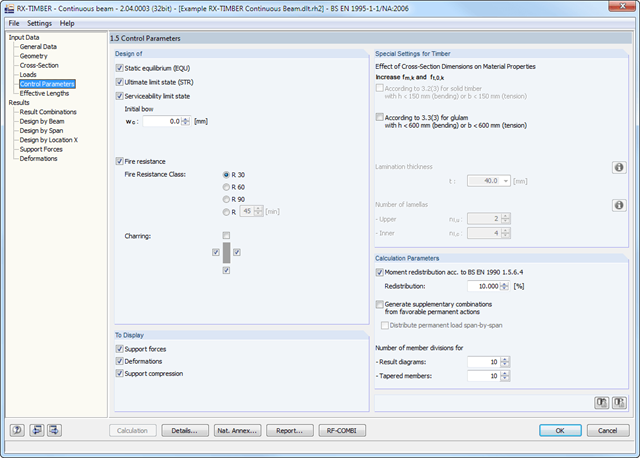
In RX-TIMBER Continuous Beam, the following calculation specifications are available:
- Design of ULS, SLS, and/or fire resistance
- Selection of designs to be performed
- Determination of displaying support forces and deformations
- Adjusting the recommended limit values for the serviceability limit state
- Definition of parameters for fire resistance design according to the simplified method
- Optional vibration design
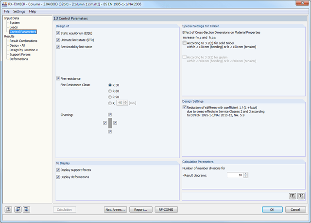
In RX-TIMBER Column, the following calculation settings are available:
- Selection of the designs to be performed (ULS, SLS, fire resistance)
- Determination of displaying support forces and deformations
- Definition of parameters for fire resistance design according to the simplified method